wings 3d draw vertices and extrude

For those of you who are artists, and eager to become into 3D art just lack the resources to go loftier-end packages similar Maya, Max, Softimage, Houdini, LightWave, etc, here is a launchpad! Wings 3D, a subdivision modeller inspired by Nendo and Mirai from Izware, has served thousands of artists across the globe as a dedicated 3D modeller. This ii-part serial demonstrates how you lot can use Wings 3D to create a model of an plane.
If you lot have access to the Internet, just visit the website (wings3d.com), and download a suitable version for your platform. For hardcore Linux fans, it's easier — either employ ArtistX (a customised version of Ubuntu 8.ten) or the Knoppix 5.3.ane alive DVD; both these distros accept Wings 3D installed and preconfigured. If yous use another distro, try the package director (Synaptic for Debian and derivatives, RPM or Yum for Ruddy Hat and its derivatives). Mark the Wings 3D package for installation, and in one case installed, fire it upwards from the terminal.
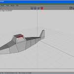
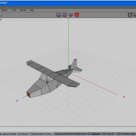
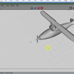
Figure 1 shows a thumbnail of the result of our design, and then yous know what we are working to accomplish.
Y'all might find the GUI unusual — Figure 2 shows what the default screen of Wings 3D looks like in one case you fire it up. Unlike other loftier-finish 3D applications, you lot do not have the screen divide into 4 views. But that does not forbid Wings 3D from being a great subdivision surface modeller. The iv cubes that you detect on the centre tiptop are the four selection modes: vertices selection, edge selection, face option and object selection.


You tin can customise the mouse function under Edit –> Preferences, to resemble other high-end applications that you may be used to. Just like in Maya, yous also accept an outliner nether the Window menu, which provides a list of all objects in the scene, stacked in order of their creation, and linked to each other.
Frequently used keyboard shortcuts
Novice artists will get stuck if not conversant with the various keyboard short-cuts, especially in applications like Wings 3D and Blender. See the post-obit lists for cursory descriptions of the various keyboard shortcuts y'all should utilise, to get the maximum out of Wings 3D.
Choice keys
- e — select edge mode
- v — select vertices style
- f — select face mode
- b — select object mode
- l — select edge loop (naturally enough, this but works on edges)
- Shift+50 — select region
- i — select similar elements
- Ctrl+Shift+i — invert selection
- Ctrl+a — select all
- space — deselect all selected elements
- + — grow option
- – — shrink choice
- F3 — select next edge lowop
- F4 — select previous border loop
- F5 — select all faces with 5 or more vertices (very useful)
View keys
- westward — toggle between shaded view and wire-frame view of model
- tab — quick smoothen shade preview
- u — car-rotate view
- a — focus view on selected elements
- 10 — align view to +10 centrality
- Shift+x — align view to -x centrality
- y — align view to +y centrality
- Shift+y — marshal view to -y axis
- z — align view to +z axis
- Shift+z — align view to -z axis
- o — toggle between perspective and orthogonal views
- up, down, left and right arrows — shift view upward, down, left and right.
- r — reset view to default view
Editing keys
- c — connect selected vertexes or edges
- d — repeat last operation
- Ctrl+z — toggle undo/redo
- Shift+Ctrl+z — redo previous operations (multiple redo possible)
- Alt+Ctrl+z — undo previous operations (multiple disengage possible)
- numeric keys on acme of keyboard 2 -> 0 — cut selected border into two to 10 edges.
File keys
- Ctrl+northward — new file
- Ctrl+o — open file
- Ctrl+l — merge file
- Ctrl+s — save file
- Shift+Ctrl+southward — salvage file as
- Ctrl+q — quit
Mouse functions
The left mouse button (LMB) selects elements, and turns them red. Clicking a selected element again deselects it. The eye mouse push button (MMB) activates camera mode. Zoom by pressing and holding the right mouse push button (RMB) or MMB, while moving the mouse.
The RMB brings up a context-sensitive card, with options for editing your selected (ruby-red) elements. Ctrl+RMB likewise activates camera mode (useful for those with 2-push mice). If you are in advanced menus, then clicking the RMB on a context menu particular with an asterisk (*) next to it will give y'all an avant-garde mesh editing option. Details are visible at the bottom of the Wings 3D screen.
Gratis-form vs. verbal modelling
In complimentary-grade modelling, you lot are non restricted to depending only on the groundwork image displayed in the viewport to model the object, but are free to make your ain changes.
Note that nigh modellers in the market offer just exact modelling, since they lack the flexibility of gratis-class modelling. Merely i or two commercial free-class modellers have been successful, similar LightWave 3D, Zbrush and Mudbox. Wings 3D can exist used for both free-course as well as exact modelling.
An inspiring modeller
Those who have delved deep into 3D modelling, and particularly organic modelling, will find that creating models of creatures, animals and humans is a keen challenge to the 3D artist. Not many 3D applications offer a gratis-form modelling arroyo like Wings 3D does.
The tools in Wings 3D lend themselves to the dexterity of the artist. What is especially sound about Wings 3D is that all the elements are flexible. Extrusion is possible not just at the face level, but besides at the border and the vertex level. Similarly, bevelling is too possible in all iii modes.
Another great reward of Wings 3D every bit an organic modeller is that there is a tweak tool, which tin can be used to reshape and conform the await and proportions of the 3D model even afterward it has been completed.
The virtual mirror tool — a great boon for organic modelling
A virtual mirroring tool is one that organic artists hunger for; note that fifty-fifty pop 3D software like Realsoft3D do non have symmetrical modelling or a virtual mirroring tool. The virtual mirror tool helps artists to create their models symmetrically. You only demand to piece of work on 1 side, and the other side is taken care of past the virtual modeller. Mirroring is possible on any axis — X, Y or Z.
The virtual mirror tool mirrors the object reverse the confront selected for operation. The greatest advantage of the virtual mirror is that it is a great fourth dimension-saver and helps in creating organic models of animals and human beings.
To mirror an object, get to the Face way by pressing the F key on the keyboard. Click on Face with the LMB. Go to the Tools menu, click the Virtual Mirror sub-card, and then the showtime entry, titled Create. Subsequently completing the model, click the Freeze pick (the third under the Virtual Mirror sub-bill of fare). This performance creates a symmetrical model ready for exporting to other formats like object and 3ds. If you are not satisfied with the mirroring, yous can even break the symmetry by selecting the second choice nether the Virtual Mirror sub-menu.
In the present example, to avoid delay, we would similar to illustrate gratis-grade modelling instead of the traditional exact way of bringing in an epitome into the image plane, to be displayed as a guide in the groundwork. We will also avoid the virtual mirror tool, since it is not required at the present juncture — I am going to illustrate a simpler technique of creating a model of the airplane in no time. For those of you interested in modelling an plane exactly, go to the website the-blueprints.com and download the blueprint of your choice. Size it in the GIMP, and import information technology into the paradigm plane.
Modelling the airplane
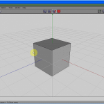
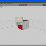
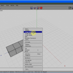
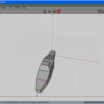
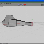
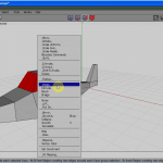
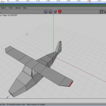
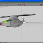
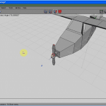
Look at Figures 3 to five. Commencement click the RMB. From the carte du jour, select a cube, and with a left click, select the confront. Press the F key if you lot are not in Face selection mode.
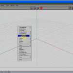
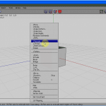
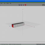
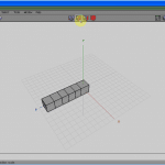
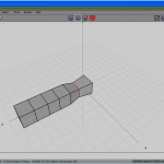
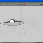
Click the RMB (see Figure half-dozen) and choose Extrude Normal (meet Figure seven) half dozen times, one after the other, to get to Figure 8.
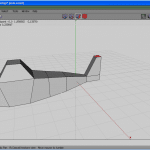
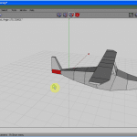
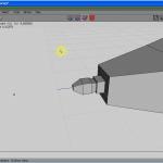
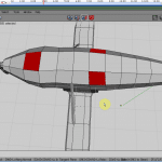
At present get to Border selection fashion (press the E key, or click the icon as seen in Figure 9). Select a top border (see Figure 10), press the L key to select the whole edge loop, and scale it down uniformly (see Figure 11).
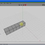
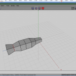
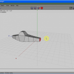
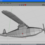
Selecting the border loops, continue scaling upward or downwards the figure, till information technology gets an approximate shape of the trunk of an airplane (see Figures 12 to 14).
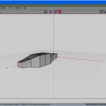
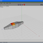
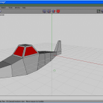
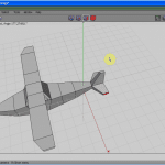
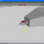
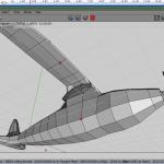
Selecting the 3rd face on the top (encounter Effigy 15), extrude it commonly (see Figure 16) to form the cockpit. Scale it uniformly for a better shape (see Effigy 17).
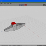
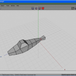
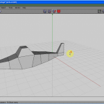
Loop-select the front body edge, and scale it in the X axis to give a improve shape to the front function of the body. Move the forepart and back edges of the cabin, to shape it upward a fleck (run into Figures xviii to twenty).
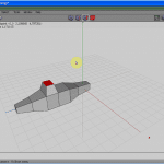
Select the face up at what is to exist the back of the aeroplane. Extrude information technology once. Loop-select the penultimate edge, and scale it down. Do the same with the last edge (see Figures 21 to 23).
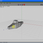
Select the top-end confront, after getting into Face selection mode by pressing the F key. Extrude information technology upwards for the top function of the tail. Shape it by scaling and moving it (see Figures 24 to 26).

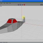
Select the polygons that form the windows of the motel — the front and the two side ones. Inset them, so as to give the shape of windows (encounter Figures 27 to 29).
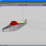
Extrude the windows out a bit. Select the two opposite polygons on top of the windows, and calibration them in the Z axis, to brand the wings protrude (encounter Figures xxx to 32).
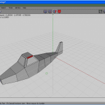
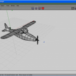
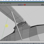
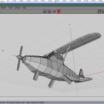
Extrude the wings and straighten them. Make ii to three extrusions, and ultimately calibration the wings at the ends. Select the two opposite polygons at the tail-terminate, extrude and scale them downwards to make the tail. Motility the tail to the right position (come across Figures 33 to 35).
To make the propeller, select the polygon at the nose tip, and inset it (see Figure 36). Extrude it one time (see Figure 37). With the functions inset, extrude, scale and move, make a propeller holder, as shown in Figure 38.
Select the meridian and bottom polygons, inset and extrude it twice, giving information technology the shape of a propeller, as shown in Figures 39 to 41.
Now, it is time to create a subdivision level, for a better look. Brand a Doo Sabin Subdivision from the RMB menu.
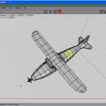
At present to create the support confined for the wings. Select two vertices on the opposite sides, and bevel them a little. Similarly, take 2 vertices below the wings, on the opposite sides, and bevel them. Select the bevelled vertex on the fly and on the lower trunk, and bridge information technology with the Bridge command. Repeat information technology for the other side (see Figures 45 to 47).
Now for the wheels: Select 3 polygons below the plane body — ane for the forepart bike, and 2 for the side wheels. Extrude the polygons to grade the supporters. Add a cylinder and shape it to class the tyre. Triplicate it to form all the 3 wheels. Position them by moving them (run into Figures 48 to l).
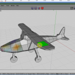
That's all for the free-class modelling, folks. I will go on the UV mapping in the next issue.

Source: https://www.opensourceforu.com/2010/10/wings-3d-gimp-quickly-modelling-texturing-airplane/
0 Response to "wings 3d draw vertices and extrude"
Post a Comment